How to Create Custom Sensors in Short Cut
by Jason Ritter | Updated: 02/27/2019 | Comments: 4
Blog Topics
Area / Application


Product Category


Corporate / News
Search the Blog
Subscribe to the Blog
Set up your preferences for receiving email notifications when new blog articles are posted that match your areas of interest.
Suggest an Article
Is there a topic you would like to learn more about? Let us know. Please be as specific as possible.
Have you ever wanted Short Cut to support more sensors? Although Short Cut supports many sensors, you may have found that the sensor you want to measure is not on the list. What do you do then? How do you add that sensor to your data logger program? In this article, we’ll discuss how you can easily create your own custom sensor files in Short Cut for use in your programs.
The Short Cut Program Generator is a software tool to help novices and experts create data logger programs in five easy steps. As an added benefit, Short Cut also creates for you a printable wiring diagram. Short Cut comes bundled with LoggerNet and PC400 software. You can also download the tool free of charge from the Short Cut download page.
The content of this article assumes that you are already familiar with the five steps to create a data logger program using Short Cut and that you are ready to create your own custom sensor file. If you’re fairly new to Short Cut, you can learn the basics by watching the videos on the Short Cut web page.
When to Create Custom Sensors
Short Cut has a Sensors folder titled “Generic Measurements” with several different types of measurements. If you know what type of output your sensor has, you may be able to use one of these generic measurements—especially if you will only be programming for that sensor once. Generic measurements, however, are probably not the best choice when you have a sensor that you use often and you don’t want to edit the generic measurement every time you use the sensor. If you create a custom sensor, it will save you time and effort later.
A Custom Sensor Example
In this example, we’ll walk through the steps of how to create a custom sensor in Short Cut. For this example, imagine the following:
- You have a favorite tensiometer that you often connect to a CR1000 datalogger to measure soil water potential.
- From the manufacturer’s specification sheet, you know that the tensiometer output is a 4 to 20 mA signal and that its measurement range is 0 to -93 kPa.
- From the tensiometer manual and past experience, you know that the tensiometer requires 12 to 24 Vdc for power and that it has a red power lead and a black signal lead.
- Because the CR1000 measures voltage instead of current, you will need to use a precision shunt resistor of 100 Ω or 125 Ω. The CURS100 100 Ohm Current Terminal Input Module, available from Campbell Scientific, can convert the 4 to 20 mA signal to a 400 to 2000 mV signal that the CR1000 can measure.
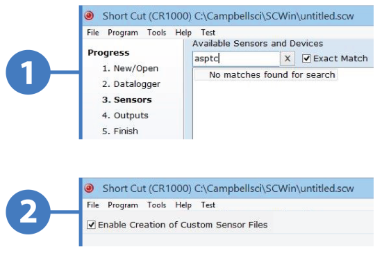
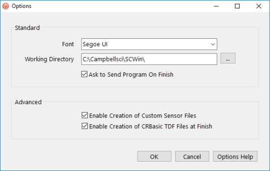
With Short Cut running, the first step to create a custom sensor is to select Tools | Options from the menu at the top of the screen. In the Options dialog box that opens, select the Enable Creation of Custom Sensor Files checkbox, and select the OK button.
To add your tensiometer to the list of sensors in Short Cut, follow these steps:
- In Short Cut, go to the New/Open screen, and select the Create New Program button.
- This takes you to the Datalogger screen. In the Datalogger Model field, select the CR1000. Select the Next button.
- On the Sensors screen, in the Available Sensors and Devices field, right-click the desired sensor. If there is a sensor on the list that is very similar to yours, select that one.
For this example, follow these steps:- Double-click the Sensors folder.
- In the Generic Measurements subfolder, select 4-20 mA Input.
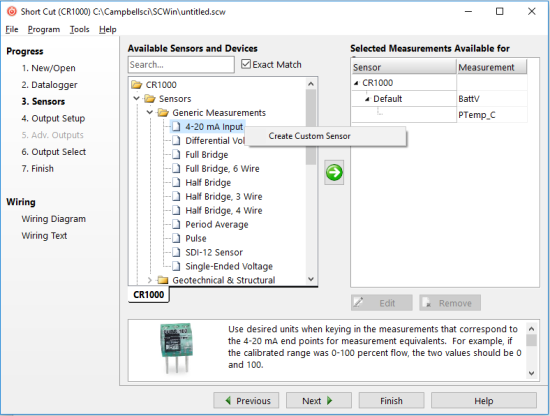
- Right-click 4-20 mA Input, and select Create Custom Sensor.
- A custom sensor dialog box opens where you can make edits to create your sensor.
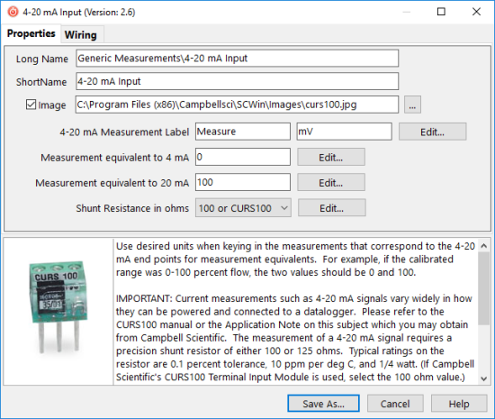
- Use the Long Name field to create a pathway to the sensor in the Available Sensors and Devices field.
- In the ShortName field, type the name that Short Cut will show for your custom sensor.
- If you have an image of the sensor on your computer, you can specify a pathway to it. Ensure that the Image checkbox is selected, and use the browse button to add the image file’s location.
- The other editable fields on the Properties tab provide Short Cut with the information it needs to generate the correct CRBasic code. For each field that you edit, select or deselect the Visible to User checkbox.
Tip: You can use this checkbox to hide values if you don’t expect they will ever change. - At the bottom of the custom sensor dialog box, in the large notes field with a scrollbar, you can type in your own description and notes.
When you’re done editing, your custom sensor screen may look something like this:
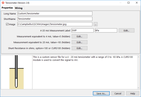
In this example, the Long Name field creates a new folder titled “Custom” where the new sensor will be found the next time you want to use it in a CR1000 program.
- To customize the sensor wiring, select the Wiring tab.
- Select the wire caption (such as High or Low) to open the Wire Properties dialog box. In this box, you can change the caption and wire color to match your sensor.
In this example, the first wire caption was changed to “Signal, Black,” and the second wire caption was changed to “Jumper wire to G”:
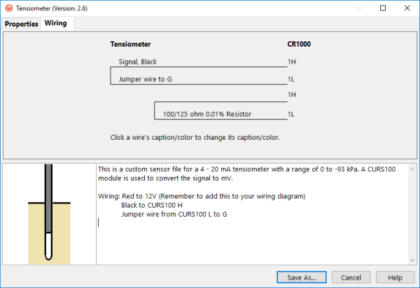
- If you find that you cannot enter some information you would like to on the Wiring tab, type it in the notes field at the bottom.
For our example, it’s not possible in the Wiring tab to add the red power lead and specify that it connects to 12V, so that information is entered in the notes field instead. - When you finish editing the custom sensor file, select the Save As button. By default, the file is saved to your Campbellsci working directory (C:\Campbellsci\SCWin\sensors) with a file extension of .SCU.
Tip: It is good practice to save the images you use for custom sensors to C:\Campbellsci\SCWin\Images.
Now that you have created your custom sensor file, it will show up in the Available Sensors and Devices field whenever you use Short Cut to write a CR1000 program. The display looks like this:
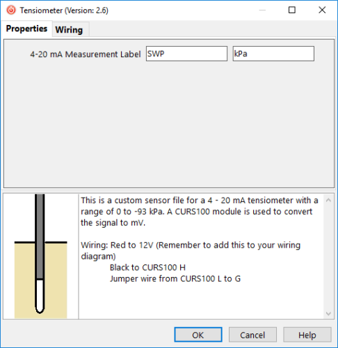
Because some of the fields were hidden from view, the only editable items in this window are the sensor name and the measurement units.
Note: If you want to use your custom sensor on other data logger models, you will have to repeat the steps outlined here. In Short Cut, be sure to select a different data logger.
Tip: Regularly make a backup of your Campbellsci working directory to preserve all of your custom sensor files, data logger programs, and especially your data logger data.
Conclusion
When you create custom sensor files in Short Cut, you enable this tool to more effectively help you create data logger programs. With a little bit of practice, you can add a whole suite of non-standard sensors to Short Cut and create data logger programs and wiring diagrams faster than ever.
If you have any custom sensor programming questions, post them below.


About the Author
 Jason Ritter was a Senior Support and Implementation Specialist at Campbell Scientific, Inc. He worked with customers to help them make the best measurement possible. Jason was a longtime fan of Campbell Scientific, having been a customer for ten years before joining the company as an application specialist. He also held the positions of soil scientist, soils product manager, soils market manager, and product group manager.
Comments
BZKM | 07/19/2020 at 05:25 PM
Hi Jason,
I am using a cr1000 data logger and loggerNet software with three sensors namely:
1. Combitech Ice monitor , output(4-20 mA) ( ice weight measuring)
2. Lambrecht Eulos, output(Rs-422) , measures(wind direction, wind speed, air temperature, relative humidity, barometric pressure)
3. Holooptics t44, output (0-5V ,digital high/low), (detecct icing)
when i go to sensors in the loggerNet software i cannot find any of these in the list. Do i need to custom add them like you told here? if yes then how to add the 2,3 sensors . i got from this video how to add sensor 1.
Thanks
Notso | 01/22/2021 at 11:20 AM
I apologize for the very late response to these questions. Unfortunately the generic measurements available in Short Cut do not support serial sensors, so the Lambrecht Eulos with RS-422 output cannot be created as a custom sensor. The CRBasic program editor will have to be used for programming the serial commands that allow the CR1000 to communicate with that sensor.
The Holo Optics t44 ice sensor has a signal that can be measured by a pulse channel on the datalogger, so the generic measurement called Pulse, set to measure high frequency with a raw measurement result of frequency could be used to create a custom sensor. It appears that other processing of the measured frequency may be needed, which cannot be done in the Pulse instruction. Additional processing might be accomplished by using User Entered in the Calculations folder of Short Cut. It may be easier however, to do the programming with the CRBasic program editor.
Dale Reid | 02/18/2022 at 01:39 AM
I'm working on a new project with a CR3000 data logger doing some meterologic monitoring.
I have an RM Young 41382VF temperature/humidity sensor, -50F to 150F 1.000 volts and 0% to 100% humidity, 1.000 v outputs.
I still have some work to do in order to understand all the Custom Sensor settings, especially as far as naming the table fields so as to be compatible with the receiving program's requirements, but having more time to understand that will no doubt solve that naming problem.
I currently have two instances of a custom sensor, one for the temperature and one for the humidity and would like to have ONE sensor which presents the data, similar to what a wind speed/direction indicator does. I've yet to get the custom setup to do that. It may have to do with my not understanding what the REV option does.
In addition I would like to make the documentation clear, and would add the power and ground connections to the wiring diagram, but so far haven't been able to figure out how to add those. I know where they go and can make notes for installation and future technician's understanding (admittedly not too complex) but is there a way to force the wiring diagram portion of the custom setup screens to allow me to specify the power and ground connections, and make the wiring color be exact to our configuration? Thank you for any additional pointers to more documentation, or any specific comments to get me to master this portion of Short Cut. Dale
Notso | 03/30/2022 at 03:57 PM
Hi Dale
Unfortunately, creating a custom sensor using the Generic folder in Short Cut does not allow for combining two sensors as a single custom sensor. We have created Short Cut files that do combine air temperature and relative humidity measurements into a single sensor, but have only done that for sensors in the Campbell Scientific product line. One of those files could probably be edited to give you exactly what you want, but that is beyond the scope of this article. We could discuss this further if you send an email to support@campbellsci.com. Include my name (Jason Ritter) in the email and it will get routed to me.
Please log in or register to comment.