This product is not available for new orders. We recommend ordering: 05108-45.
| Services Available |
|---|
Overview
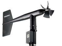
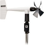
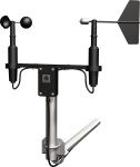
The 05103-45 Wind Monitor is a lightweight instrument that measures wind speed and wind direction. It is designed to prevent ice buildup, allowing the sensor to provide accurate measurements in harsh alpine conditions. Manufactured by R. M. Young, this wind monitor is cabled for use with Campbell Scientific dataloggers.
Read MoreBenefits and Features
- Smaller propeller diameter minimizes vibration at high wind speeds
- Discourages ice-buildup with a black sensor housing that is covered with an ice-resistant coating
- Compatible with most Campbell Scientific data loggers
- Uses stainless-steel, precision-grade ball bearings for the propeller shaft and vertical shaft bearings
- Rugged enough for harsh environments
- Compatible with the LLAC4 4-channel Low-Level AC-Conversion Module, which increases the number of anemometers one data logger can measure
- Compatible with the CWS900-series interfaces, allowing it to be used in a wireless sensor network
Images

Similar Products
Detailed Description
The 05103-45 is constructed from rigid UV-stabilized thermoplastic, and has stainless steel and anodized aluminum fittings. The thermoplastic material resists corrosion from sea air environments and atmospheric pollutants. It uses stainless-steel precision-grade ball bearings for the propeller shaft and vertical shaft bearings.
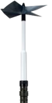
Designed for harsh alpine conditions, the 05103-45 has a smaller propeller diameter than the other wind monitor models, which minimizes vibration at high wind speeds. To discourage ice buildup, the sensor's housing is black and covered with an ice-resistant coating.
The 05103-45 measures wind speed with a helicoid-shaped, four-blade propeller. Rotation of the propeller produces an ac sine wave that has a frequency directly proportional to wind speed. The ac signal is induced in a transducer coil by a six-pole magnet mounted on the propeller shaft. The coil resides on the non-rotating central portion of the main mounting assembly, eliminating the need for slip rings and brushes.
Wind direction is sensed by the orientation of the fuselage-shaped sensor body, which is connected to an internal potentiometer. The datalogger applies a known precision excitation voltage to the potentiometer element. The output is an analog voltage signal directly proportional to the azimuth angle.
Compatibility
Note: The following shows notable compatibility information. It is not a comprehensive list of all compatible or incompatible products.
Dataloggers
| Product | Compatible | Note |
|---|---|---|
| 21X (retired) | ||
| CR10 (retired) | ||
| CR1000 (retired) | ||
| CR1000X (retired) | ||
| CR10X (retired) | ||
| CR200X (retired) | ||
| CR206X (retired) | ||
| CR211X (retired) | ||
| CR216X (retired) | ||
| CR23X (retired) | ||
| CR295X (retired) | ||
| CR300 (retired) | ||
| CR3000 (retired) | ||
| CR310 | ||
| CR500 (retired) | Measurements are typically processed for output with the Wind Vector instruction, which is not present in the CR500. | |
| CR5000 (retired) | ||
| CR510 (retired) | ||
| CR800 (retired) | ||
| CR850 (retired) | ||
| CR9000 (retired) | Measurements are typically processed for output with the Wind Vector instruction, which is not present in the CR9000. | |
| CR9000X (retired) |
Additional Compatibility Information
Mounting
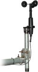
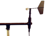
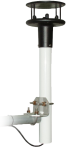
The 05103-45 can be attached to a crossarm via a 17953 NU-RAIL fitting or CM220 Right Angle Mounting Bracket. Alternatively, it can be attached to the top of a CM106B or stainless-steel tripod via the CM216 Sensor Mounting Kit.
Wind Profile Studies
Wind profile studies measure many wind sensors. For these applications, the LLAC4 4-Channel Low Level AC Conversion Module can be used to increase the number of Wind Monitors measured by one data logger. The LLAC4 allows data logger control ports to read the wind speed sensor’s ac signals instead of using pulse channels. Data loggers compatible with the LLAC4 are the CR200(X) series (ac signal ≤1 kHz only), CR800, CR850, CR1000, CR3000, and CR5000.
Data Logger Considerations
The 05103-45's propeller uses one pulse count channel on the data logger. Its wind vane requires one single-ended channel and access to an excitation channel (the excitation channel can be shared with other high impedance sensors).
Programming
The 05103-45's propeller is measured by the PulseCount Instruction in CRBasic and by Instruction 3 (Pulse Count) in Edlog. The wind vane is measured by the BrHalf Instruction in CRBasic and by Instruction 4 (Excite-Delay-SE) in Edlog. The measurements are typically processed for output with the Wind Vector instruction (not present in the CR500 or CR9000 but is present in the CR9000X).
Specifications
| Operating Temperature Range | -50° to +50°C (assuming non-riming conditions) |
| Mounting Pipe Description |
|
| Propeller Diameter | 14 cm (5.5 in.) |
| Overall Height | 37 cm (14.6 in.) |
| Main Housing Diameter | 5 cm (2.0 in.) |
| Overall Length | 55 cm (21.7 in.) |
| Weight | 1 kg (2.2 lb) |
Wind Speed |
|
| Range | 0 to 100 m/s (0 to 224 mph) |
| Accuracy | ±0.3 m/s (0.6 mph) or 1% of reading |
| Starting Threshold | 1.0 m/s (2.2 mph) |
| Distance Constant | 2.7 m (8.9 ft) 63% recovery |
| Output |
ac voltage (three pulses per revolution) 90 Hz (1800 rpm) = 8.8 m/s (19.7 mph) |
| Resolution | (0.0980 m s-1)/(scan rate in seconds) or (0.2192 mph)/(scan rate seconds) |
Wind Direction |
|
| Mechanical Range | 0 to 360° |
| Electrical Range | 355° (5° open) |
| Accuracy | ±3° |
| Starting Threshold | 1.1 m/s (2.4 mph) at 10° displacement |
| Distance Constant | 1.3 m (4.3 ft) 50% recovery |
| Damping Ratio | 0.3 |
| Damped Natural Wavelength | 7.4 m (24.3 ft) |
| Undamped Natural Wavelength | 7.2 m (23.6 ft) |
| Output |
|
| Voltage | Power switched excitation voltage supplied by data logger |
Videos & Tutorials

Frequently Asked Questions
Number of FAQs related to 05103-45-L: 5
Expand AllCollapse All
-
This depends on what is broken. Typically, Campbell Scientific can repair the unit, and the user does not have to purchase a new one.
-
The measurement instructions will likely remain the same. However, in addition to the multiplier and offset, the type of pulse may change for the wind speed, and the excitation voltage may change for the wind direction. For an explanation of how the data logger needs to be programmed, see the instruction manual.
-
- Using Short Cut, click the applicable wind direction sensor in the Selected Sensors list of the Outputs screen.
- The two output options enabled are Sample and WindVector. Select WindVector.
- The WindVector instruction has output options. Select an option with mean wind direction in it.
-
To incorporate a sensor that is compatible with wireless sensor interfaces into a wireless network, a CWS900-series wireless sensor interface is needed, as well as an A205 CWS-to-PC interface to configure it.