More accurate in soils with high bulk electrical conductivity


Overview
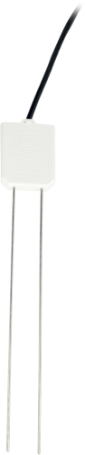
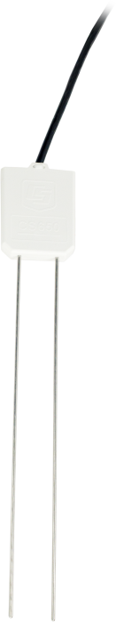
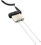
The CS650 is a multiparameter smart sensor that uses innovative techniques to monitor soil volumetric water content, bulk electrical conductivity, and temperature. It outputs an SDI-12 signal that many of our dataloggers can measure.
Read MoreBenefits and Features
- More accurate water content measurements in soils with bulk EC up to 3 dS m-1 without performing a soil-specific calibration
- Larger sample volume reduces error
- Measurement corrected for effects of soil texture and electrical conductivity
- Estimates soil-water content for a wide range of mineral soils
- Versatile sensor—measures dielectric permittivity, bulk electrical conductivity (EC), and soil temperature
Images
Similar Products

Detailed Description
The CS650 consists of two 30-cm-long stainless steel rods connected to a printed circuit board. The circuit board is encapsulated in epoxy and a shielded cable is attached to the circuit board for datalogger connection.
The CS650 measures propagation time, signal attenuation, and temperature. Dielectric permittivity, volumetric water content, and bulk electrical conductivity are then derived from these raw values.
Measured signal attenuation is used to correct for the loss effect on reflection detection and thus propagation time measurement. This loss-effect correction allows accurate water content measurements in soils with bulk EC ≤3 dS m-1 without performing a soil specific calibration.
Soil bulk electrical conductivity is also calculated from the attenuation measurement. A thermistor in thermal contact with a probe rod near the epoxy surface measures temperature. Horizontal installation of the sensor provides accurate soil temperature measurement at the same depth as the water content. Temperature measurement in other orientations will be that of the region near the rod entrance into the epoxy body.
Compatibility
Note: The following shows notable compatibility information. It is not a comprehensive list of all compatible or incompatible products.
Dataloggers
| Product | Compatible | Note |
|---|---|---|
| CR1000 (retired) | ||
| CR1000X (retired) | ||
| CR300 (retired) | ||
| CR3000 (retired) | ||
| CR310 | ||
| CR350 | ||
| CR6 | ||
| CR800 (retired) | ||
| CR850 (retired) |
Additional Compatibility Information
RF Considerations
External RF Sources
External RF sources can affect the probe’s operation. Therefore, the probe should be located away from significant sources of RF such as ac power lines and motors.
Interprobe Interference
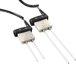
Multiple CS650 sensors can be installed within 4 inches of each other when using the standard datalogger SDI-12 “M” command. The SDI-12 “M” command allows only one probe to be enabled at a time.
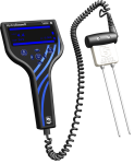
Installation Tool
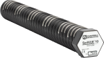
The CS650G makes inserting soil-water sensors easier in dense or rocky soils. This tool can be hammered into the soil with force that might damage the sensor if the CS650G were not used. It makes pilot holes into which the rods of the sensors can then be inserted.
Datalogger Considerations
Compatible Contemporary Dataloggers
| CR200(X) Series | CR800/CR850 | CR1000 | CR3000 | CR9000X |
 |
|
|
|
Compatible Retired Dataloggers
| CR500 | CR510 | CR10 | CR10X | 21X | CR23X | CR9000 | CR5000 | CR7X |
|
|
|
|
|
|
Specifications
| Measurements Made | Soil electrical conductivity (EC), relative dielectric permittivity, volumetric water content (VWC), soil temperature |
| Required Equipment | Measurement system |
| Soil Suitability | Long rods with large sensing volume (> 6 L) are suitable for soils with low to moderate electrical conductivity. |
| Rods | Not replaceable |
| Sensors | Not interchangeable |
| Sensing Volume | 7800 cm3 (~7.5 cm radius around each probe rod and 4.5 cm beyond the end of the rods) |
| Electromagnetic |
CE compliant Meets EN61326 requirements for protection against electrostatic discharge and surge. |
| Operating Temperature Range | -50° to +70°C |
| Sensor Output | SDI-12; serial RS-232 |
| Warm-up Time | 3 s |
| Measurement Time | 3 ms to measure; 600 ms to complete SDI-12 command |
| Power Supply Requirements | 6 to 18 Vdc (Must be able to supply 45 mA @ 12 Vdc.) |
| Maximum Cable Length | 610 m (2000 ft) combined length for up to 25 sensors connected to the same data logger control port |
| Rod Spacing | 32 mm (1.3 in.) |
| Ingress Protection Rating | IP68 |
| Rod Diameter | 3.2 mm (0.13 in.) |
| Rod Length | 300 mm (11.8 in.) |
| Probe Head Dimensions | 85 x 63 x 18 mm (3.3 x 2.5 x 0.7 in.) |
| Cable Weight | 35 g per m (0.38 oz per ft) |
| Probe Weight | 280 g (9.9 oz) without cable |
Current Drain |
|
| Active (3 ms) |
|
| Quiescent | 135 µA typical (@ 12 Vdc) |
Electrical Conductivity |
|
| Range for Solution EC | 0 to 3 dS/m |
| Range for Bulk EC | 0 to 3 dS/m |
| Accuracy | ±(5% of reading + 0.05 dS/m) |
| Precision | 0.5% of BEC |
Relative Dielectric Permittivity |
|
| Range | 1 to 81 |
| Accuracy |
|
| Precision | < 0.02 |
Volumetric Water Content |
|
| Range | 0 to 100% (with M4 command) |
| Water Content Accuracy |
|
| Precision | < 0.05% |
Soil Temperature |
|
| Range | -50° to +70°C |
| Resolution | 0.001°C |
| Accuracy |
|
| Precision | ±0.02°C |
Documents
Technical Papers


. This activity is helpful when troubleshooting.")
Downloads
CS650 / CS655 Firmware v.2 (429 KB) 02-12-2015
Current CS650 and CS655 firmware.
Note: The Device Configuration Utility and A200 Sensor-to-PC Interface are required to upload the included firmware to the sensor.
Frequently Asked Questions
Number of FAQs related to CS650: 50
Expand AllCollapse All
-
The CS650-series sensors have several logical tests built into their firmware to ensure that the sensors do not report a number that is known to be erroneous. Erroneous readings are either outside the sensor’s operational limits or outside of published accuracy specifications.
A reported value of NAN or 9999999 does not necessarily mean that there is a problem with the sensor hardware. The conditions outlined below can lead to a value of NAN or 9999999 for permittivity and volumetric water content.
SDI-12 communications issue
If all of the following are true, there is likely an issue with the SDI-12 communications between the sensor and the data logger: the sensor is being polled with an M1! SDI-12 command, the permittivity value reported is NAN, and subsequent values are all zeroes or never change. Possible causes include the following:
- The sensor is not powered. Check to make sure that the red wire is well connected to a 12 Vdc source and that the black wire is connected to data logger ground.
- The sensor signal wire is not connected properly. Ensure that the green wire is well connected to the control port specified in the data logger program.
- The sensor has an SDI-12 address that does not match the data logger program.
- The sensor has cable or lightning damage.
Calculated permittivity is less than 0 or greater than 88
The equation used to convert period average and electrical conductivity values to permittivity is a three-dimensional surface with two independent variables and eleven coefficients, plus an offset. Some rare combinations of period and electrical conductivity result in a permittivity calculation that is less than air (1) or greater than water at 0°C (88). These rare combinations are not expected when the sensor is in soil.
Bulk electrical conductivity (EC) is greater than 1.14 dS/m
When bulk electrical conductivity is greater than 1.14 dS/m, the solution EC is greater than 3 dS/m, which is the upper limit for accurate readings with the CS650. When this occurs, the soil is considered out-of-bounds and will report a value of NAN or 9999999 for both permittivity and volumetric water content.
Calculated permittivity is less than 80% of the permittivity limit
A permittivity limit based on the bulk electrical conductivity (EC) reading is used to determine whether the bulk EC at saturation exceeds the sensor’s operational limit. That permittivity limit is calculated and compared to the permittivity reading. If the measured permittivity is more than 20% beyond the permittivity limit, both permittivity and volumetric water content are reported as NAN or 9999999. This is the most common cause of NAN values with the CS650-series sensors, and it occurs because of the soil properties and not because of a sensor malfunction.
-
The electrical conductivity (EC) of sea water is approximately 48 dS/m. The CS650 can measure permittivity in water with EC between 0 and 3 dS/m. EC readings become extremely unstable at conductivities higher than 3 dS/m and are reported as NAN or 9999999. Because EC is part of the permittivity equation, an EC reading of NAN leads to a permittivity reading of NAN as well. Thus, the CS650 cannot provide good readings in sea water.
With regard to sea ice, the electrical conductivity drops significantly when sea water freezes and the permittivity changes from approximately 88 down to approximately 4, as the water changes from a liquid to a solid state. With both EC and permittivity falling to levels that are within the CS650 measurement range, the sensor is expected to give valid readings in sea ice. The sensor is rugged and can withstand the cold temperatures. However, as the ice melts, there will be a point at which the electrical conductivity becomes too high to acquire a valid reading for either permittivity or electrical conductivity.
-
No. The equation used to determine volumetric water content in the firmware for the CS650 and the CS655 is the Topp et al. (1980) equation, which works for a wide range of mineral soils but not for organic soils. In organic soils, the standard equations in the firmware will overestimate water content.
When using a CS650 or a CS655 in organic soil, it is best to perform a soil-specific calibration. For details on performing a soil-specific calibration, refer to “The Water Content Reflectometer Method for Measuring Volumetric Water Content” section in the CS650/CS655 manual. A linear or quadratic equation that relates period average to volumetric water content will work well.
-
Because the reported volumetric water content reading is an average taken along the entire length of the rods, the sensor should be fully inserted into the soil. Otherwise, the reading will be the average of both the air and the soil, which will lead to an underestimation of water content. If the sensor rods are too long to go all the way into the soil, Campbell Scientific recommends inserting the rods at an angle until they are fully covered by soil.
-
Mine tailings are highly corrosive and have high electrical conductivity. Some customers have successfully used water content reflectometers, such as the CS650 or the CS655, to measure water content in mine tailings by coating the sensor rods with heat-shrink tubing. This affects the sensor output, and a soil-specific calibration must be performed. Care must be taken during installation to avoid damaging the heat-shrink tubing and exposing the sensor’s rods. In addition, covering the sensor’s rods invalidates the bulk electrical conductivity reading. Unless the temperature reading provided by the CS650 or the CS655 is necessary, a better option may be to use a CS616 with coated rods.
-
The permittivity of saturated sediments in a stream bed is expected to read somewhere between 25 and 42, while the permittivity of water is close to 80. A CS650 or CS655 installed in saturated sediments could be used to monitor sediment erosion. If the permittivity continuously increases beyond the initial saturated reading, this is an indication that sediment around the sensor rods has eroded and been replaced with water. A calibration could be performed that relates permittivity to the depth of the rods still in the sediment.
-
No. The abrupt permittivity change at the interface of air and saturated soil causes a different period average response than would occur with the more gradual permittivity change found when the sensor rods are completely inserted in the soil.
For example, if a CS650 or a CS655 was inserted halfway into a saturated soil with a volumetric water content of 0.4, the sensor would provide a different period average and permittivity reading than if the probe was fully inserted into the same soil when it had a volumetric water content of 0.2.
-
The CS650/CS655 manual gives a temperature correction that works in coarse sand, but it should be used cautiously with other soil types. If a temperature correction is required, it is best to determine a soil-specific temperature correction.
When correcting for temperature, the following effects contribute to the sensor output:
- The effect of temperature on the measurement electronics inside the sensor head. This is a relatively small effect compared to other temperature effects.
- The change in the dielectric permittivity of water with temperature. At 0°C, the permittivity of water is approximately 88, at 20°C it is approximately 80, and at 70°C it is approximately 64. If the sensor is in a soil at any given water content, the changing permittivity of water will cause the period average at 0°C to be higher than it is at 20°C. The same soil will have a lower period average at 70°C than at 20°C. In other words, the sensor will overestimate water content at colder temperatures and underestimate it at warmer temperatures. However, that is only true if electrical conductivity is negligible.
- The change in water content as bound water is captured and released. In soils with high clay content, some of the water is partially or fully immobilized by electrical charges on the surface of the clay minerals. The amount of bound water is temperature dependent and may have a small effect on the sensor readings.
- The temperature effect of bulk electrical conductivity (EC) on period average. Bulk electrical conductivity increases with temperature; as it increases, it slows down the period average.
The interaction of these effects may be complicated. For example, with increasing temperature, two things happen at the same time: the falling permittivity of water is decreasing the period average, and the increasing EC is increasing the period average. The net result as to whether the period average goes up or down depends on how conductive the soil is and the contributions of the other temperature effects.
-
Yes. There is surge protection built into the sensor electronics. The sensor survives a surge of 2 kV at 42 ohm line-to-ground on digital I/O and 2 kV at 12 ohm line-to-ground on power. It also survives a surge of 2 kV at 2 ohm line-to-ground on the rods.
If additional surge protection is required, consider using the SVP100 Surge Voltage Protector DIN Rail with Mounting Hardware.
-
Damage to the CS650 or the CS655 electronics or rods cannot be repaired because these components are potted in epoxy. Cable damage, on the other hand, may possibly be repaired. For more information, refer to the Repair and Calibration page.
Case Studies

Everglades National Park is the largest tropical wilderness in the United States and was created......read more