


Overview
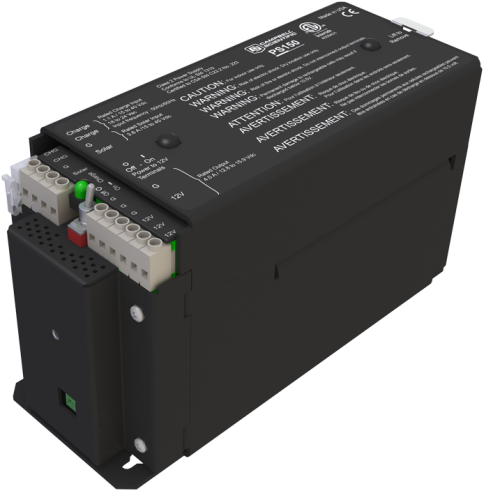
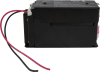
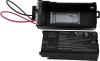
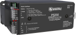
The PS150 is a 12 Vdc power supply that includes a rechargeable 7 Ah valve-regulated lead-acid (VRLA) battery and charging regulator. Charging power for the PS150 is typically supplied by an unregulated solar panel, AC/AC transformer, or AC/DC converter. The PS150 provides charging with temperature compensation for optimal charging and battery life. A maximum power point tracking algorithm is incorporated for solar inputs to maximize available solar charging resources.
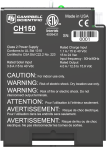
The PS150 is ETL certified. The ETL Mark is proof of product compliance to North American safety standards.
Read MoreBenefits and Features
- Protects against high-amperage and high-voltage damage to power supply
- Battery reversal protection
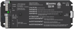
- Allows simultaneous connection of two charging sources (e.g., solar panel, ac wall charger)
- ETL listed Class 2 power supply
Images


CAD Files:
Similar Products
Detailed Description
The PS150 is a micro-controller-based smart charger with temperature compensation that optimizes battery charging and increases the battery's life. Two input terminals enable simultaneous connection of two charging sources. They also incorporate a maximum power point tracking algorithm for solar inputs that maximizes available solar charging resources.
The PS150 has several safety features intended to protect the charging source, battery, charger, and load devices. Battery-reversal protection is included, as well as ESD and surge protection on all of the PS150 inputs and outputs.
The PS150 replaced the PS100.
Specifications
| Operational Temperature | -40° to +60°C (VRLA battery manufacturers state that “heat kills batteries” and recommend operating batteries at ≤ 50°C.) |
| Dimensions | 19.3 x 7.6 x 10.6 cm (7.5 x 3 x 4.2 in.) |
CHARGE - CHARGE Terminals (AC or DC Source) |
|
| AC | 18 to 24 VRMS (internally limited to 1.2 Amps RMS) |
| DC | 16 to 40 Vdc (internally limited to 0.85 Adc) |
SOLAR Terminals (Solar Panel or Other DC Source) |
|
| -NOTE- | Battery voltages below 8.7 V may result in < 3.0 A current limit because of fold-back current limit. |
| Input Voltage Range | 15 to 40 Vdc |
| Maximum Charging Current | 4.0 Adc typical (3.2 to 4.9 Adc depending upon individual charger) |
Quiescent Current |
|
| No Charge Source Present | 160 μA at 13.7 Vdc |
| No Battery Connected | 930 μA at 30 V input voltage (ac or dc) |
Battery Charging |
|
| -NOTE- | The "T" represents temperature in degrees Celsius. |
| FLOAT Charging | Vbatt(T) = 13.65 V - (24 mV) x (T - 25) + (0.24 mV) x (T - 25)2 |
| Accuracy | ±1% (on charging voltage over -40° to +60°C) |
Power Out (+12 Terminals) |
|
| Voltage | Unregulated 12 V from battery (4.65 A solid-state circuit breaker) |
| Standards | ETL Listed Class 2 power supply |
Compatibility
Note: The following shows notable compatibility information. It is not a comprehensive list of all compatible or incompatible products.
Dataloggers
| Product | Compatible | Note |
|---|---|---|
| 21X (retired) | ||
| CR10 (retired) | ||
| CR1000 (retired) | ||
| CR10X (retired) | ||
| CR200X (retired) | ||
| CR206X (retired) | ||
| CR211X (retired) | ||
| CR216X (retired) | ||
| CR23X (retired) | Typically, a CR23X datalogger uses its integrated rechargeable base instead of the PS150. However, the PS150 can be used if the data logger has a low-profile base or if the battery base has been disconnected. | |
| CR295X (retired) | ||
| CR3000 (retired) | Typically, a CR3000 datalogger uses its integrated rechargeable base instead of the PS150. However, the PS150 can be used if the data logger has a low-profile base or if the battery base has been disconnected. | |
| CR500 (retired) | ||
| CR5000 (retired) | Typically, a CR5000 datalogger uses its integrated rechargeable base instead of the PS150. However, the PS150 can be used if the data logger has a low-profile base or if the battery base has been disconnected. | |
| CR510 (retired) | ||
| CR6 | ||
| CR800 (retired) | ||
| CR850 (retired) | ||
| CR9000 (retired) | ||
| CR9000X (retired) |
Power Supplies
| Product | Compatible | Note |
|---|---|---|
| SP10 | ||
| SP10R-L (retired) | ||
| SP20 | ||
| SP20R-L (retired) | ||
| SP50-L | ||
| SP5-L | ||
| SP90-L |
Additional Compatibility Information
Enclosure Considerations
A desiccated, non-condensing environment is required. The PS150 includes built-in keyhole flanges for mounting to the backplate of a Campbell Scientific enclosure.
Adapters
The PS150 is compatible with the A100 null-modem adapter and the A105 adapter for additional 12 V output terminals. The A100 Null Modem Adapter connects and powers two Campbell Scientific peripherals via two CS I/O 9-pin connectors configured as a null modem. This is useful in linking different communications technologies, such as telephone to radio, at sites that do not have a data logger. The A105 adapter may be used to provide additional 12 V and ground terminals where the power supply is used to power several devices.
Documents
Technical Papers
Frequently Asked Questions
Number of FAQs related to PS150: 5
Expand AllCollapse All
-
The PS100, PS150, and PS200 models take in AC or DC power from a wall transformer or a solar panel. The internal regulator controls the charge to the battery to make sure the battery doesn’t become overcharged (based on temperature).
If the switch is on, the voltage from the battery will flow back out from the regulated battery to the loads; however, the voltage on that battery may be 11.9 V, 13.2 V, or some other value that the battery happens to be at. It is important to understand that the voltage will not always be exactly 12.0 Vdc. Rather, the voltage will float up or down as the battery is recharged or depleted.
-
Yes. The G and 12V terminals on the charge regulator are used to connect the black and red wires that connect with the green connector, which provides power to the data logger.
-
The voltage from a solar panel will fluctuate throughout the day.
If AC power is being used, the voltage is usually stable.
The voltages coming into the regulator inputs are controlled so that the battery won’t be overcharged (and thus ruined by boiling out the electrolyte). If the battery connected to the regulator is good, the highest voltage you will likely see is just above 14 Vdc in the extreme cold, but normally it should be around 13.2 Vdc.
If you have a nearly dead battery (to be checked with a voltmeter) or a battery with shorted cells, you will see a very low battery voltage. The lowest voltage you will see on the data logger data is usually about 10.0 V because the data logger will shut down near that level and then wait for the voltage to increase to an 11- or 12-volt level.
The ripple voltage is a few millivolts flowing into the battery, but the battery should filter out most of that noise, providing a pretty stable voltage.
-
The CH150 or PS150 will pull power only from the source with the highest voltage at that moment. For example, the regulator will take the 20 W input from the 24 Vdc wall transformer rather than from the 18 V 50 W solar panel—even during the day. If the power goes out, the 50 W solar panel will charge during the day with no charging at night.
-
Look for a stamp on top of the battery. The stamp may be in a date format of YYMMDDXX where:
- YY is the year.
- MM is the month.
- DD is the day.
- XX is the manufacturing plant.
This indicates the age of the battery.
Case Studies

In 1922, when the intact tomb of Tutankhamen was discovered in Egypt's Valley of the......read more