Four-way, research-quality radiometer; thermistor and Pt-100 built in


Overview
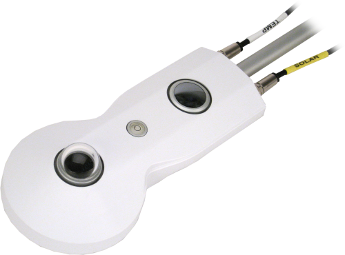
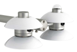
The CNR4, manufactured by Kipp & Zonen, is a research-grade net radiometer that measures the energy balance between incoming and outgoing radiation. Our dataloggers measure the CNR4's output. This net radiometer offers a professional solution for scientific-grade energy balance studies.
Read MoreBenefits and Features
- Research-grade performance
- Meniscus dome on upper long-wave detector allows water droplets to easily roll off of it and increases field of view to nearly 180°
- Internal temperature sensors provide temperature compensation of measurements
- Drying cartridge helps keep the electronics dry
- Compatible with the CNF4 ventilation unit with heater that reduces formation of dew and melts frost
- Separate outputs of short-wave and long-wave infrared radiation for better accuracy and more thorough quality assurance
- Solar shield reduces thermal effects on the sensors
Images

Detailed Description
The CNR4 consists of a pyranometer and pyrgeometer pair that faces upward and a complementary pair that faces downward. The pyranometers and pyrgeometers measure shortwave and long-wave infrared radiation, respectively.
The upper long-wave detector of the CNR4 has a meniscus dome that allows water droplets to easily roll off of it. The dome shape also increases the field of view to nearly 180° instead of 150° for a flat window.
The CNR4 contains both an internal thermistor and an internal Pt-100 RTD. Typically, the thermistor makes the instrument housing temperature measurements used to compensate the infrared readings. Alternatively, the RTD can provide these measurements if a CR3000 or CR5000 datalogger is used.
The CNR4 has a solar shield that reduces the thermal effects on both the short-wave and long-wave measurements. A drying cartridge helps keep the radiometer’s electronics dry. The CNF4, an optional ventilation unit with heater, can be fitted onto the CNR4 to minimize the formation of dew as well as melt frost.
Specifications
| Sensor | Two thermopile pyranometers, two pyrgeometers, Pt100 RTD, and thermistor |
| Measurement Description | Measures incoming and outgoing short-wave and long-wave radiation |
| Response Time | < 18 s |
| Temperature Dependence of Sensitivity | < 4% (-10° to +40°C) |
| Sensitivity | 5 to 20 μV W-1 m2 |
| Non-Linearity | < 1% |
| Tilt Error | < 1% |
| Directional Error |
< 20 W m-2 (pyranometer) Angles up to 80° with 1000 W/m2 beam radiation |
| Operating Temperature Range | -40° to +80°C |
| Compliance | Conforms to the CE guideline 89/336/EEC 73/23/EEC. |
| Height | 6.6 cm (2.6 in.) dome-to-dome |
| Width | 11.1 cm (4.4 in.) |
| Length |
|
| Weight | 850 g (30.0 oz) without cable |
Pyranometer |
|
| Spectral Range | 305 to 2800 nm |
| Uncertainty in Daily Total | < 5% (The uncertainty values are for a 95% confidence level.) |
| Output Range | 0 to 15 mV (The output range is typical for atmospheric applications.) |
Pyrgeometer |
|
| Spectral Range | 4500 to 42,000 nm |
| Uncertainty in Daily Total | < 10% (The uncertainty values are for a 95% confidence level.) |
| Output Range | ±5 mV (The output range is typical for atmospheric applications.) |
Compatibility
Note: The following shows notable compatibility information. It is not a comprehensive list of all compatible or incompatible products.
Dataloggers
| Product | Compatible | Note |
|---|---|---|
| CR1000 (retired) | When using a CR1000, the internal temperature of the CNR4 should be measured with the internal thermistor. | |
| CR3000 (retired) | ||
| CR6 | ||
| CR800 (retired) | ||
| CR850 (retired) |
Additional Compatibility Information
Mounting
To avoid shading or reflections and to promote spatial averaging, the CNR4 should be mounted at least 1.5 m above the ground or crop canopy and away from all obstructions or reflective surfaces that might adversely affect the measurement.
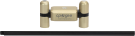
The CNR4 can be attached to a vertical pipe or horizontal crossarm. To do this, first connect the radiometer to its mounting rod. The mounting rod then attaches to the pipe or crossarm via the 26120 Net Radiation Sensor Mounting Kit. The kit includes adjustment screws for leveling the CNR4. The 26120 can withstand winds up to 120 mph.
Data Logger Considerations
Four differential channels or four single-ended channels are used to measure the radiation components. A voltage excitation channel and an additional single-ended channel are required to measure the thermistor. If the RTD is used to provide the temperature compensation measurement, a current excitation channel (only available on the CR3000 and CR5000) and a differential channel are required.
Documents
Brochures
Manuals
Downloads
CR1000X CNR4 Program Controlling the CNF4 Heater/Ventilator v.1 (4 KB) 17-10-2019
CR1000X program measures the CNR4 and controls the CNF4 heater/ventilator based on environmental conditions, and monitors the CNF4 tachometer. The program uses an EE181 temperature and relative humidity sensor and a 03002 Wind Sentry to provide the measurements for determining when to turn the fan and heater on and off. An A21REL-12 relay switches power to the CNF4.
CR1000X CNR4 Program using Thermistor v.1 (2 KB) 17-10-2019
CR1000X program that uses differential terminals to measure the four radiation outputs and one excitation terminal and one single-ended terminal to measure the thermistor. The program measures the sensors every 1 second, performs the online processing of the data, and stores processed data to a data table called cnr4_data once every 60 minutes. It also stores the raw time-series data from CNR4 to data table called cnr4_ts.
CR3000 CNR4 Program using Pt-100 v.1 (2 KB) 17-10-2019
CR3000 program measures the Pt-100 sensor for the body temperature of the CNR4. This program requires four differential channels to measure the four radiation outputs, one current excitation channel, and one differential channel for Pt-100 measurement. It measures the sensors every 1 second, performs the online processing of the data, and stores the processed data to a data table called cnr4_data once every 60 minutes. It also stores the raw time-series data from CNR4 to data table called cnr4_ts.
Frequently Asked Questions
Number of FAQs related to CNR4-L: 11
Expand AllCollapse All
-
Yes. The signal from this sensor is not great enough to compensate for its dissipation because of the cable length.
-
As of June 2013, all of our current and retired net radiation sensors can be mounted using this kit. These include:
- Current sensors: CNR4-L, NR-LITE2-L, and NR01-L
- Retired sensors: CNR1, CNR1-L, CNR2-L, NR-LITE-L, and Q7.1-L
-
Only one 4WPB100 is needed to measure the internal PRT in the radiometer.
-
If there is direct sun, the daily albedo graph is a U shape, because it’s a function of sun angle. If it’s a cloudy day without any direct sun, the daily albedo graph is more flat.
-
Mount the net radiometer so that no shadow will be cast on it at any time of day from obstructions such as trees, buildings, the mast, or the structure on which it is mounted.
Campbell Scientific recommends installing a net radiometer in an open area, away from the main weather station structure on a separate vertical mast. If it is necessary to install this sensor on the main tall tower (30 ft or taller), the sensor should be installed at the top of the tower. In the northern hemisphere, the sensor should be facing south. In the southern hemisphere, the sensor should be facing north. If the tower uses a solar power system (that is, solar panels), ensure that the solar panels are installed away from the main tower.
-
The CR1000 requires a 4WPB100 to measure the internal PRT. (Data loggers such as the CR3000 and CR5000 have the necessary PRT bridge module built in to measure the PRT.) Note that the CNR4-L also includes an internal thermistor, which can be directly measured by the CR1000. Because of this, when using a CR1000, Campbell Scientific typically recommends monitoring the internal temperature of the CNR4-L using its internal thermistor instead of the PRT.
-
Because of the loss of IR radiation, nearly all thermopile instruments typically have a negative offset. This offset is most easily visible at night-time, when a small negative value is read instead of zero. This same offset is present during the daytime, but it is not as visible because of the large solar signal.
Another common issue involves leveling an instrument. Leveling a thermopile instrument can cause errors in the direct beam component because the cosine response is not correct. These errors are more notable when the sun is close to the horizon because the angle is so shallow.
-
Technically, because albedo is the fraction of the sun’s radiation reflected from a surface, albedo cannot be quantified at night.
When calculating albedo, it is important to remember that when radiation readings are very low, there is a significantly large error associated with the ratio. For example, as the sun drops to a lower position on the horizon, the ratio of reflected and incoming radiation becomes somewhat meaningless.
Albedo can be calculated from the simultaneous incoming and reflected pyranometer readings, with the average stored. Both of these pyranometer signals should be in a differential input mode.
- At night-time, the upper pyranometer faces a cold sky, which causes the domes to cool and the readings to be negative. (For example, there may be readings of -2 to -7 W/m2, depending on the sky conditions.)
- In contrast, the lower pyranometer faces the ground, which could be warmer or cooler. The readings are unlikely to be positive, and may even be -2 W/m2.
In principle, two negative values could result in a night-time albedo of 0.5.
Because of the input resolution, noise, and offsets of the data logger used, it is highly unlikely that any individual pyranometer reading is exactly zero. Depending upon the configuration used, any positive irradiation values recorded by the data logger as less than 2 W/m2 may, actually, be less than zero.
If an upper pyranometer reading, a lower pyranometer reading, or both is/are less than 2 W/m2, the albedo value should be described as “undefined” or “invalid.”
Another approach is to just not calculate albedo when the flux values get small. For example, set a cut-off point for the minimum flux value that will be used in albedo calculations.
If solar position is being calculated, one other approach is to use a solar position calculation, such as 1° above the horizon.
-
Most Campbell Scientific sensors are available as an –L, which indicates a user-specified cable length. If a sensor is listed as an –LX model (where “X” is some other character), that sensor’s cable has a user-specified length, but it terminates with a specific connector for a unique system:
- An –LC model has a user-specified cable length for connection to an ET107, CS110, or retired Metdata1.
- An –LQ model has a user-specified cable length for connection to a RAWS-P weather station.
If a sensor does not have an –L or other –LX designation after the main model number, the sensor has a set cable length. The cable length is listed at the end of the Description field in the product’s Ordering information. For example, the 034B-ET model has a description of “Met One Wind Set for ET Station, 67 inch Cable.” Products with a set cable length terminate, as a default, with pigtails.
If a cable terminates with a special connector for a unique system, the end of the model number designates which system. For example, the 034B-ET model designates the sensor as a 034B for an ET107 system.
- –ET models terminate with the connector for an ET107 weather station.
- –ETM models terminate with the connector for an ET107 weather station, but they also include a special system mounting, which is often convenient when purchasing a replacement part.
- –QD models terminate with the connector for a RAWS-F Quick Deployment Station.
- –PW models terminate with the connector for a PWENC or pre-wired system.
-
Not every sensor has different cable termination options. The options available for a particular sensor can be checked by looking in two places in the Ordering information area of the sensor product page:
- Model number
- Cable Termination Options list
If a sensor is offered in an –ET, –ETM, –LC, –LQ, or –QD version, that option’s availability is reflected in the sensor model number. For example, the 034B is offered as the 034B-ET, 034B-ETM, 034B-LC, 034B-LQ, and 034B-QD.
All of the other cable termination options, if available, are listed on the Ordering information area of the sensor product page under “Cable Termination Options.” For example, the 034B-L Wind Set is offered with the –CWS, –PT, and –PW options, as shown in the Ordering information area of the 034B-L product page.
Note: As newer products are added to our inventory, typically, we will list multiple cable termination options under a single sensor model rather than creating multiple model numbers. For example, the HC2S3-L has a –C cable termination option for connecting it to a CS110 instead of offering an HC2S3-LC model.
Case Studies
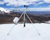
Currently, the Andean tropical glaciers are in an accelerated process of retreat. These glaciers are......read more
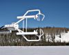
Scientists and land-use managers have long recognized the importance of forest lands for their role......read more